Article Journals
УДК 681.26:631.3:001.4
Development,
researches and implementation of hydraulic type measuring devices for
determination of weight and traction characteristics of agricultural machinery in the field
Mitrofanov O., Director; Lilevman I., head of the laboratory; Lilevman O., senior researcher (South Ukrainian Branch of L.Pogorilyy UkrNDIPVT)
Podolskyy M. – Ph.D., Associate professor (Kherson National Technical University)
The results of the development, research and introduction in agricultural machines testing of weight (strength measuring instruments of hydraulic structures of South Ukrainian Branch of L. Pogorilyy UkrNDIPVT and search operations in the direction of hydraulic mechanisms for measuring traction characteristics are cited.
Keywords: agricultural machines, tests, hydraulic weight measuring devices, design development, research, implementation, hydraulic draft meter
Ключові слова: сільськогосподарські машини, випробування, прилади ваговимірювальні гідравлічні, розробка конструкції, дослідження, апробація, впровадження, гідравлічні тягоміри
Introduction.Rendering the agricultural trials the quality of which correspond to updated requirements and, at the same time, the economic need to reduce their term is impossible without improvement of research methods and related measuring instruments. In this case it is important to address the technical and methodological problems to determine the machines’ weight and traction specifications. The purpose of this article - to acquaint testers and manufacturers of agricultural machinery with the latest research and development results of South Ukrainian Branch of L. Pogorilyy UkrNDIPVT involving Kherson National Technical University on the said topic.
Determination of problem and objectives. The problem is that in the situation where there are no fixed scales for weighing bulky heavy loads (in the field, in areas of machine and tractor mills, livestock and poultry farms, customs warehouses), using the portable weighing instruments of mass production (car weighs, electronic crane scales, mechanical dynamometer, etc.) is associated with the need for time-consuming preparatory work which requires the use of lifting hardware or limited in many cases by a large area of contact with drivers supporting surface [1-6].
Therefore, to render tests at a sufficient level
of quality it is relevant to solve problems regarding:
- development of design, manufacturing, research and introduction of testing
portable and small in size and weight weighing instruments which during the
trials outside the research institutions and test centers could provide a
definition of weight (force) characteristics of the machines in a convenient
way with the least cost labor, energy and without the above mentioned
restrictions;
- the use of these devices as a means of strength measuring;
- conducting search operations towards the use of hydraulic mechanisms to measure the traction of tractors and agricultural traction resistance.
The main research material.
To solve this problem in the South Ukrainian Branch of L. Pogorilyy UkrNDIPVT in recent years a number of researches [7, 8] were conducted. At the first stage hydraulic weighing device design ПВГ-5was designed with mechanical dial gauge, experimental model was manufactured and its technical properties were tested, the results were published in the magazine [9].
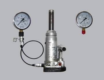
Fig. 1 - hydraulic weighing device ПВГ-5
The use of the ПВГ-5instrument in the field shown along with several unconditional advantages compared with mobile means measuring the weight (mass) of serial production the drawbacks of the device resulted in the lack of discrete reference dial scale and the need to strain eyes while reading the testimony (especially between the scale graduation), due to this the subjective factor reduces the accuracy of measurements. This aroused a need to improve the design of the device, and it was equipped with gauges with digital display and accuracy not lower than 0.5.
At the next phase of researches experimental models of hydraulic weighing devices ПВГ-5Е (Fig. 2) and ПВГ-10Е (Fig. 3) were developed and manufactured with the upper limit of the measurement under 5 tons and 10 tons.
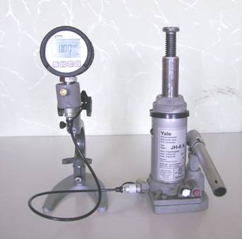
Fig. 2 - hydraulic weighing device ПВГ-5Е
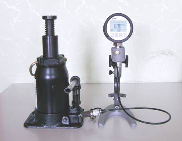
Fig. 3 - hydraulic weighing device ПВГ-10Е
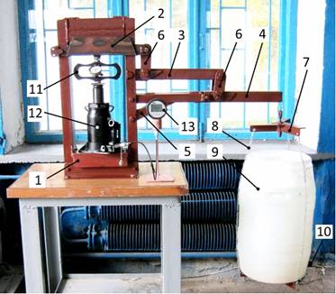
The basis for the design of devices ПВГ-5Е and ПВГ-10Е (Fig. 4) is a pallet jacks 1 carrying capacity under 5 tons and 10 tons. The platform 2 of each of the jacks has channel 3 between its outer surface and the surface that forms the bottom of the piston cavity 4 in the case 5 under a power piston 6. To the channel 3 on the outside of jack’s platform 2 via coupling 7 with hydraulic fluid leakage preventing valve and high pressure hydraulic hose 8 of required length electronic digital manometer 9 Servis Junior of Parker company production (Germany) on threaded connections with sealing gaskets is attached.
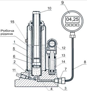
1- manual hydraulic jack; 2- platform; 3 - channel; 4 - piston cavity; 5 -
case; 6 - power piston; 7- coupling with the working fluid leakage preventing
valve; 8 - high-pressure hose; 9 - electronic digital manometer; 10 - load platform;
11 - a control valve; 12 - discharge cylinder lever;
13 - discharge piston; 14 - discharge cylinder body;
15-filler plug with breather
Fig. 4 - Scheme of hydraulic weighing instruments
ПВГ-5Е and ПВГ-10Е
The functional principle of the device is as follows: when the device is lifting a machine weight load via the load receiving platform 10 and the power piston 6 is transferred to the hydraulic fluid in the piston cavity 4 and creates an appropriate pressure. The hydraulic fluid pressure is measured by electronic digital gauge 9.
Transfer of hydraulic fluid pressure values in the equivalent weight load values is carried through calibration of device with a special installation, which was also designed and made by specialists of the branch (Fig. 5).
The installation consists of a frame 1, levers of first 2, second 3 and third 4 stages, holder 5, rods 6, traverse 7, slings 8, water vessel 9, the drain valve 10.
To study the dependence of the pressure of the working fluid in the device ПВГ on the value of acting on it loads and for calibration the device this device is installed on the lower horizontal beam of the frame 1 and between the load receiving deck and lever the first stage 2 a reference load dynamometer 11 is placed, resting on them with its thrust washers. The vessels with water 9 through a system of levers 2, 3, 4 press with some force on the reference load dynamometer 11, while it, in its turn, with the same force presses the rod 12 of the jack. The pressing force value is recorded by reference dynamometer, and the corresponding to this power the working fluid pressure value in the device is displayed on its gauge 13.
1 - frame; 2 - lever of the first degree; 3 - lever
of the second degree; 4 - lever of the third degree; 5 -holder; 6 - rods; 7-
traverse; 8 - slings; 9 - vessel for water; 10 - drain valve; 11 - reference load
dynamometer; 12 - hydraulic jack belonging
to the ПВГ device; 13- digital electronic gauge belonging to the ПВГ device
Fig. 5 - Installation for the study of working fluid pressure
in devices ПВГ-5Е and ПВГ-10Е dependence on the value of loads applied to them
and for calibration of these devices
Installation solves the problem of stabilizing of force applying to ПВГ devices during their studies and calibration. This is due to the power piston displacement compensation device under the force applied by reference dynamometer by respective movement of the reference dynamometer. At that the reference dynamometer deformation does not change, so its pressing force on the device does not change either.
In the course of the work the research on the dynamics of the working fluid pressure in the ПВГ devices under sustainable weight load was conducted. The study determined that the start of action of sustainable weight load on devices during 1.5-2.0 minutes decreases the working fluid pressure in them, and then comes unlimited in time pressure stabilization and the ability to record the manometer readings during calibration and conducting them by measurements.
Installation (Fig. 5) provides the opportunity to study and re-calibrate in the modes of increasing force pressing on the equipment (load) and its reduction (discharge). In the mode of loading vessel 9 is gradually filled with water, ensuring the pressing force on the device according to step calibration reference dynamometer characteristics and in the mode of discharge the process occurs by draining water from the vessel by tap 10.
Dependence of fluid pressure in piston cavities of ПВГ-5Е and ПВГ-10Е devices on loads acting on the devices is illustrated in the diagram (Fig. 6), where the dynamics growth of fluid pressure with increasing loads and vice versa fluid pressure drop with a decrease in load is clearly traced.
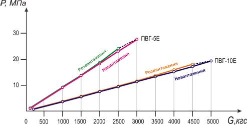
Fig. 6 - Diagram of the working fluid
pressure (P)
in piston cavities devices ПВГ-5Е and ПВГ-10Е on
the magnitude of loads acting on the devices (G)
Because of the elastic hysteresis in power link equipment, as well as friction forces between their parts, load lines, in general, does not coincide with the lines of discharge, which is typical for means of measuring forces, and as a special case - measuring the weight (mass) [1].
Taking into account that the ratio between the load acting on the device, and equivalent pressure of the working fluid in the device is non-linear, for the determination of the weight (force) load on the device it is necessary to apply the method of interpolation.
The program of this work included the research on the stability of the ПВГ readings under different ambient temperature and it was found out that within the permissible during the test measurement accuracy (± 2%) [3-4] and in the prescribed temperature range operation of ПВГ devices (-10 ÷ 40) оС testimony of temperature influence was not detected. There is no need to adjust readings of ПВГ depending on the ambient temperature.
Also specifications were defined and operational documents for ПВГ devices were developed. These documents contain a description of designation and scope, technical data, structure and principles of work, safety requirements, preparation for operation, work order and configuration of devices.
According to the program of ПВГ devices implementation in practice of agricultural research and testing in the field:
a)metrological certification of ПВГ devices together with SE "Kherson Scientific-Production Center of Standardization, Metrology and Certification" was conducted the results of which state that the devices meet the requirements of regulatory documents and are approved for use, and the error of weight (force) load is 2%, i.e. does not exceed the maximum measurement error specified characteristics of agricultural machinery and tractors [3-4];
b)b) a "Methodology of determining the weight and load on the steered wheels of tested agricultural machines using weighing hydraulic construction equipment of South Ukrainian branch of L. Pogorilyy UkrNDIPVT” as the most common weight characteristics of tested tractors, self-propelled machines and other mobile equipment was developed The method meets the basic requirements of standards to determine the weight characteristics of the tested vehicles and safety requirements of the work;
c)c) testing of ПВГ devices and methods of their application as to the accuracy of weight characteristics of agricultural machines, convenience and safety of the work using these devices was conducted (Fig. 7, 8).
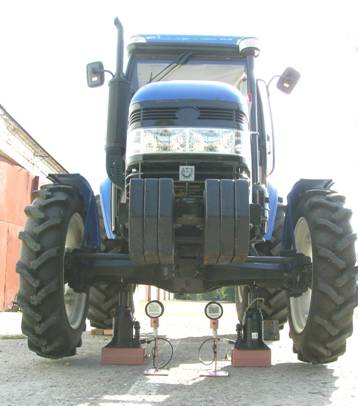
Fig. 7 – Testing ПВГ-10Еdevices during
weighing the tractor ДТЗ-804
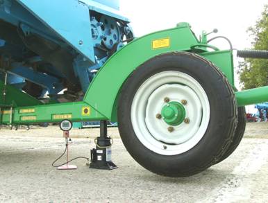
Fig. 8 - Testing ПВГ-10Еdevices while weighing
ВЖУ-7cart with corn harvester КМС-8
18 machines were tested, including those referred to in the table.
Results of weighing machines with ПВГ instruments, being tested,
and of motor-truck scales РП15Ш13
|
Name of machine |
Weight of machine determined using ПВГ-10Е and ПВГ-5Е devices, kg
|
Machine weight, determined by using РП15Ш13 scales, kg |
The difference between weight determined with ПВГ devices and the mass determined with RP15SH13 scales, % |
|
Cart ВЖУ-7 with corn harvester КМС-8 |
3518 |
3495 |
+ 0,66 |
|
Multipurpose pneumatic seeders «Вега-8» |
3167 |
3190 |
- 0,75 |
|
Tractor ДТЗ-804 |
3490 |
3515 |
- 0,71 |
|
Grain harvester КЗС-250 «Скіф-250» |
15566 |
15428 |
+ 0,89 |
|
Front loader PN 936 |
10415 |
10500 |
- 0,81 |
The results of testing showed that the difference between the mass of each of the machine, defined with ПВГ device and motor-truck scales РП15Ш13 of mass production did not exceed permissible error of measurement of weight (± 2%) [3, 4].
Developments carried out in the course of research are protected by 4 patents for utility models and certificate of the author's work.
At the final stage of the research the search on the use of ПВГ devices as strength measuring means and hydraulic tools application for measuring the tractive effort registering their dynamics was conducted.
On the results of this phase the following is performed:
a) experiments on the use of ПВГ instruments to measure the working bodies pressing force on the ground (Fig. 9) and loading force of machine on coupling were conducted. It was determined that the use of ПВГ devices to measure these parameters enables the measurement by one person with significantly reduced energy costs and significantly improves the accuracy of measurement and provides measurement process;
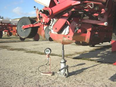
Fig. 9 -
Measurement of shovel load on
the soil with the use of the ПВГ-5Е device
b) two mock samples of hydraulic draft indicator were designed and manufactured: one with electronic digital pressure gauge (Fig. 10) and the other with sensor and the working fluid dynamics pressure logger (Figure 11).
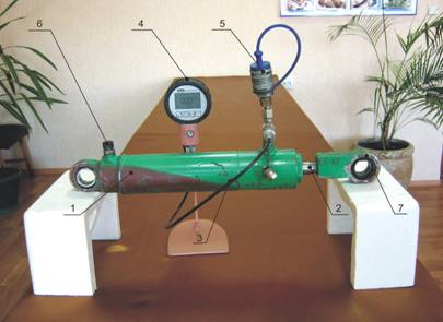
1- double-acting hydraulic cylinder; 2 -
rod; 3 - high
pressure hose; 4 - digital electronic gauge of Servis Junior Parker company;
5 - quick disconnect coupler; 6-breather; 7-eyelet
Fig. 10 – hydraulic draft indicator with
electronic digital pressure gauge
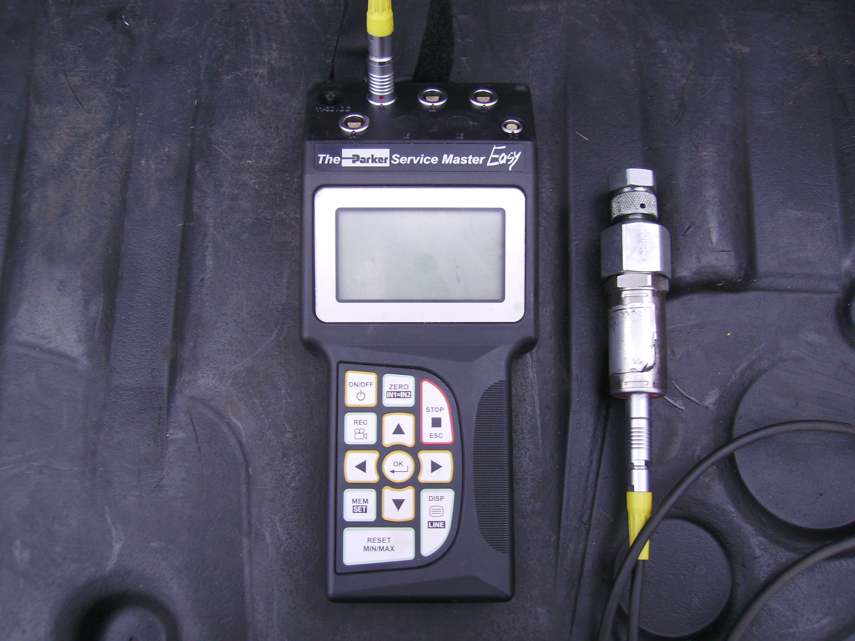
Рис. 11 – sensor and the working fluid dynamics pressure logger by Parker company
To make measurement draft indicator is installed between the power means and the tested machine (Fig. 12) and during experiments traction force (traction resistance force) is transmitted through the power piston of the draft indicator to the working fluid in its piston cavity and creates the appropriate pressure. The pressure of the working fluid depends on the traction force (traction resistance force) and is measured by a pressure gauge. Transfer of pressure fluid values in the equivalent values of the traction force (traction resistance force) is performed according to the results of draft indicator calibration.
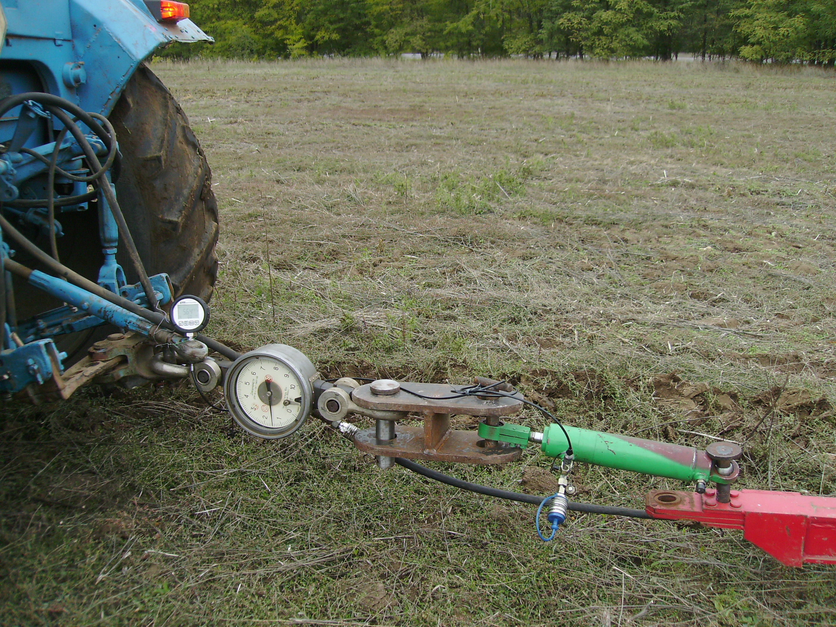
Fig. 12 - Testing of hydraulic draft indicator with electronic digital manometer
compared with mechanical pressure gauge action
According to the preliminary testing results the first sample of draft indicator (with electronic digital pressure gauge) was very sensitive and was able to display the current value of fluid pressure, but "remembered" and depicted only the peak (minimum and maximum) values.
Preliminary testing of a second sample (with sensor and electronic working fluid pressure dynamics logger) showed that it registers dynamics pressure of the working fluid in the device in digital form and with appropriate computer programs it is possible to depict this dynamic in tabular and graphical form (Fig. 13).
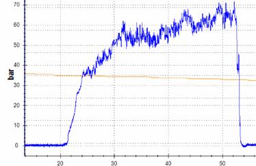
Fig. 13 - Graphic
form of
the working fluid pressure dynamics in the hydraulic draft indicator
According to the data, using the integral method and calibration characterization of draft indicator the estimated value of traction is calculated.
So the search work on the use of hydraulic mechanisms for measuring and registration of traction characteristics has a positive result that suggests to consider it appropriate and worthy to continue to improve the design of hydraulic draft indicator, the study of metrology and performance, software development and methodological support for the use of these devices in the machines testing.
Conclusions.
1. Two experimental
models of hydraulic weighing instruments (ПВГ-5Е, ПВГ-10Е)) and
installation of calibration are designed, manufactured and tested, providing
the definition of weight (force) characteristics of vehicles outside areas of
scientific research institutions and test centers in handy manner without the
use of lifting equipment and supporting vehicles, with the least cost of labor
and energy.
2. Operational documentation instruments and methods of use of these devices are developed.Their metrological certification and testing are conducted, according to the results of which devices are allowed to use, and error in determining the characteristics of weight does not exceed the maximum permissible error of measurement of weight characteristics of agricultural machinery and tractors.
3. A search on the use of ПВГ devices as strength measuring means and application of hydraulic mechanisms for measuring traction resistance and traction with the registration of their dynamics are made. Results of the work give reason to believe it appropriate to continue.
4. Developments, being the results of research, are protected by 4 patents for utility models and by certificate of the author's work.
Literature
1. Измерение массы, объема и плотности : учебное пособие / С. И. Гаузнер [и др.]. - М : Издательство стандартов, 1972. – 623 с.
2. М 014. 100. 00 РЭ Весы автомобильные переносные. Руководство по эксплуатации. НПО «МЕТА», 2008. – 41 с.
3. ГОСТ 26025-83 Машины и тракторы сельскохозяйственные и лесные. Методы измерения конструктивных параметров - Введ. 1984-01-01- М: Изд-во стандартов, 1984.- 5с.
4. ГОСТ 27922-88 Машины землеройные. Методы измерения масс машин в целом, рабочего оборудования и составных частей – Введ. 1988-11-29. - М: Изд-во стандартов, 1988.- 10 с.
5. ДСТУ ГОСТ 7075-2003 Тракторы сільськогосподарські. Методи випробування – Введ. 2003-05-13. - К.: Держспоживстандарт України, 2003. – 14 с.
6. ГОСТ 23734-98 Тракторы промышленные. Методы испытаний – Введ. 2002-09-01. - К.: Госстандарт Украины, 1995. – 16 с.
7. Розробити конструкцію та виготовити прилад гідравлічного типу для визначення вагових характеристик сільськогосподарських машин в польових умовах і провести його апробацію: звіт про НДР / Південно-Українська філія УкрНДІПВТ ім. Л Погорілого; кер. О. П. Митрофанов. – ДР 0111U001579 – Херсон, 2010.- 50 с.
8. Дослідження та провайдинг технічних засобів визначення вагових характеристик сільськогосподарських машин в польових у мовах : звіт про НДР (заключний) / Південно-Українська філія УкрНДІПВТ ім. Л Погорілого; кер. О. П. Митрофанов. – ДР 0114U003553 – Херсон, 2013.-126 с.
9. Митрофанов, О. П. Ваговимірювальний прилад для випробувань і досліджень сільгосптехніки в польових умовах / О. П. Митрофанов, І. Й. Лілевман, О. Й. Лілевман, З. М. Терещук, М. І. Подольський // Техніка і технології АПК. – 2011. - № 4. – С. 25-28.
У статті наведені результати розробки, дослідження та впровадження в практику випробувань сільськогосподарських машин приладів ваговимірювальних (силовимірювальних) гідравлічних конструкції Південно-Української філіїУкрНДІПВТ ім. Л. Погорілого та пошукових робіт в напрямку використання гідравлічних механізмів для вимірювання тягових характеристик.
Аннотация. В статье приведены результаты разработки, исследования и внедрения в практику испытаний сельскохозяйственных машин приборов весоизмерительных (силоизмерительных) гидравлических конструкции Южно-Украинского филиала УкрНИИПИТ им. Л. Погорелого и поисковых работ в направлении использования гидравлических механизмов для измерения тяговых характеристик.


- Нам 75!
- AGRO Challenge
- Про інститут
- Контакти
- Тематичний план 2023 р.
- Напрямки діяльності
- Наукове супроводження
- УкрНДІПВТ пропонує
- Орган затвердження типу
- Державний реєстр
- Регістр технічних засобів
- Видання
- "Техніка і технології АПК"
- Навчання
- Конференції
- День Поля
- Виставки
- Вакансії
Ми в соцмережах: